Friday, October 2, 2009

Effect of Adding a Zero

Consider the second-order system given by:

G(s) =1 / ((s+p1)(s+p2)) p1 > 0, p2 > 0

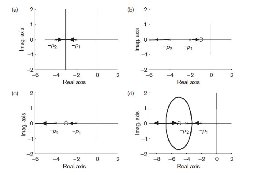
The poles are given by s = –p1 and s = –p2 and the simple root locus plot for this system is shown in Figure . When we add a zero at s = –z1 to the controller, the open-loop transfer function will change to:

G1(s) =K(s+z1) / ((s+p1)(s+p2)) , z1>0

adding zeroEffect of adding a zero to a second-order system root locus.

We can put the zero at three different positions with respect to the poles:

1. To the right of s = –p1 Figure (b)

2. Between s = –p2 and s = –p1 Figure (c)

3. To the left of s = –p2 Figure (d)

(a) The zero s = –z1 is not present.

For different values of K, the system can have two real poles or a pair of complex conjugate poles. Thus K for the system can be overdamped, critically damped or underdamped.

(b) The zero s = –z1 is located to the right of both poles, s = – p2 and s = –p1.

Here, the system can have only real poles. Hence only one value for K to make the system overdamped exists. Thus the pole–zero configuration is even more restricted than in case (a). Therefore this may not be a good location for our zero,

since the time response will become slower.

(c) The zero s = –z1 is located between s = –p2 and s = –p1.

This case provides a root locus on the real axis. The responses are therefore limited to overdamped responses. It is a slightly better location than (b), since faster responses are possible due to the dominant pole (pole nearest to jω-axis) lying further from the jω-axis than the dominant pole in (b).

(d) The zero s = –z1 is located to the left of s = –p2.

By placing the zero to the left of both poles, the vertical branches of case (a) are bent backward and one end approaches the zero and the other moves to infinity on the real axis. With this configuration, we can now change the damping ratio and the natural frequency . The closed-loop pole locations can lie further to the left than s = –p2, which will provide faster time responses. This structure therefore gives a more flexible configuration for control design. We can see that the resulting closed-loop pole positions are considerably influenced by the position of this zero. Since there is a relationship between the position of closed-loop poles and the system time domain performance, we can therefore modify the behaviour of closed-loop system by introducing appropriate zeros in the controller.

Poles and Zeros

Poles and Zeros of a transfer function are the frequencies for which the value of the transfer function becomes infinity or zero respectively. The values of the poles and the zeros of a system determine whether the system is stable, and how well the system performs. Control systems, in the most simple sense, can be designed simply by assigning specific values to the poles and zeros of the system. Let’s say we have a transfer function defined as a ratio of two polynomials:

H(s)=N(s)/D(s)

Where N(s) and D(s) are simple polynomials. Zeros are the roots of N(s) (the numerator of the transfer function) obtained by setting N(s) = 0 and solving for s.Poles are the roots of D(s) (the denominator of the transfer function), obtained by setting D(s) = 0 and solving for s. [1]

The poles and zeros are properties of the transfer function, and therefore of the differential equation describing the input-output system dynamics. Together with the gain constant K they completely characterize the differential equation, and provide a complete description of the system. A system is characterized by its poles and zeros in the sense that they allow reconstruction of the input/output differential equation. In general the system dynamics may be represented graphically by plotting their locations on the complex s-plane, whose axes represent the real and imaginary parts of the complex variable s (pole-zero plots). For the stability of a linear system, all of its poles must have negative real parts,that is they must all lie within the left-half of the s-plane. A system having one or more poles lying on the imaginary axis of the s-plane has non-decaying oscillatory components in its homogeneous response, and is defined to be marginally stable. [2]

Thursday, October 1, 2009

Incremental encoders !!!!!!!!!

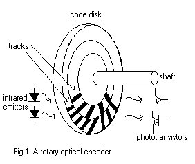
Incremental encoders are position feedback devices that provides incremental counts. Thus, incremental encodersprovide relative position, where the feedback signal is always referenced to a start or home position. For incrementalencoders, each mechanical position is uniquely defined. The current position sensed is only incremental from the last position sensed. Incremental encoders are also non-contacting optical, rotary, quadrature output device. •These incremental encodersare also called optical encoders or optical incremental encoders because they utilizes optical technology. Optical incremental encoders are highly sort after as position feedback devices due to its durability and ability to achieve high resolution. Avago’s optical incremental encoders are exceptionally recognized for its reliability and accuracy.
encoder
encoder

Synchro?? how is it Related to stepper motor!!!!!

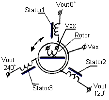
A SYNCHRO is a motor like device containing a rotor and a stator and capable of converting an angular position into an electrical signal, or an electrical signal into an angular position. A Synchro can provide an electrical output (at the Stator) representing its shaft position or it can provide a mechanical indication of shaft position in response to an applied electrical input to its stator winding.


STEPPER MOTOR

A stepper motor is a “digital” version of the electric motor. The rotor moves in discrete steps as commanded, rather than rotating continuously like a conventional motor. When stopped but energized, a stepper (short for stepper motor) holds its load steady with a holding torque. Wide spread acceptance of the stepper motor within the last two decades was driven by the ascendancy of digital electronics. Modern solid state driver electronics was a key to its success. And, microprocessors readily interface to stepper motor driver circuits.

Synchro

Sunday, July 26, 2009

CINCINNATI MILACRON T3 ROBOT ARM


Cincinnati Milacron built large industrial robots primarily for welding industry. It was one of the first companies to change from hydraulic to electric robots. Milacron pioneered the first computerized numerical control (CNC) robot with improved wrists and the tool centre point (TCP) concepts. The first hydraulic machine, the introduced in 1978. It closely resembled the General Electric Man-mate, ITT arm, and other predecessors (Sullivan 1971). Constructed of cast aluminium, it is available in two models of 6-axes revolute jointed arms. The largest, the T3-776, uses ballscrew electric drives to power the shoulder and elbow pitch. The ballscrews replaced the hydraulic cylinders originally used on the T3 robots. The elbow is a classical example of intermediate drive elbow. The same techniques, only upside down, appear in the shoulder. Shoulder yaw is provided by the standard bullgear on a base mounted motor drive. End users have discovered that ballscrews are not sufficiently reliable and are pressuring for an alternators. The eventual disappearance of ballscrews in industrial robots seems inevitable.

CONTROL SYSTEM

The T3 robotic arms is controlled using a Hierarchical Control System.A Hierarchical control system is partitioned vertically into levels of control. The basic comand and control structure is a tree, configured such that each computational module has a single superior, and one or more subordinate modules. The top module is where the highest level decisions are made and the longest planning horizon exists. Goals and plans generated at this highest level are transmitted as commands to the next lower level where they are decomposed into sequences of subgoals. These subgoals are in turn transmitted to the next lower control decision level as sequences of less complex but more frequent commands. In general,the decisions and corresponding decompositions at each level take into account: (a) conrmands from the level above, (b) processed sensory feedback information appropriate to that control decision level, and (c) status reports from decision control modules at the next lower control level.


The figure shown above depicts the schematic block diagram of the integrated control structure as configured on the Cincinnati Milacron T3 Robot. The system is configured in the hierarchical manner and includes five major subsystems:
(1) The Real-Time Control System (RCS)
(2) The commercial. T3 Robot equipment
( 3 ) the End-Effector System
(4) The Vision System
(5) The Watchdog Safety System

The Real-Time Control System as shown in figure is composed of four levels:
(1) The Task Level
(2)The Elemental-Move Level
(3) The Primitive Level
(4)The T3 Level.

The Task, Elemental-Move and Primitive levels of the controller are considered to be Generic Control Levels. That is, these levels would remain essentially the same regardless of the particular robot (commercial or otherwise) being used. The T3 Level, however ,uses information and parameters particular to the T3 Robot and is, therefore, unique to the T3 Robot. The Joystick shown provides an alternate source of commands to the Primitive Level for manual control of the robot and is not used in conjunction with the higher control levels .The T3 Controller shown in figure is part of the T3 Robot equipment as purchased from Cincinnati Milacron. This controller is subordinate to the T3 Level of the RCS and communicates through a special interface.
The End-Effector System consists of a two fingered gripper equipped with position and force sensing .The gripper is pneumatically actuated and servo controlled by a controller which is subordinate to the Primitive Level of the RCS. There are three sensory systems on the robot:

1. The finger force and position sensors on the gripper which report data to the End Effector Controller
2. The 3 point Angle Acquisition System which reports data to the T3 Controller, the T3 Level of the RCS and to the Watchdog Safety System
3. The Vision System which reports data to the Elemental-Move Level of the RCS.
4. Of the sensor systems, the vision system is obviously the most complex. It performs
sophisticated image processing which requires substantial computational time.

The Watchdog Safety System does not fit directly into the hierarchical control structure. It is an independent system which monitors robot motions and compares them to previously defined limits in position, velocity and acceleration. The Watchdog System has the power to stop the robot if any limits are exceeded and consequently monitors both the mechanical and control systems of the robot.

PARTS OF THE REAL TIME CONTROL SYSTEM
(1)Task Level
The Task Level interfaces with the Workstation Level above it and the Elemental-Move Level below it. In the current configuration, the Task Level has no direct interfaces with sensory systems. The Task Level receives commands from the Workstation Level in terms of objects to be handled and named places in the workstation.
For example, the task might be to find a certain part on the tray at the load/unload station, pick it up and put it in the fixture on the machine tool. This task could be issued as one command from the Workstation Level to the Task Level of the RCS.

(2)Elemental-Move Level
The E-Move Level interfaces with the Task Level above it and the Primitive Level below it. In addition, the E-Move Level interfaces with the Vision System from which it acquires part position and orientation data. The E-Move Level receives commands from the Task Level which are elemental segments of the Task Level command under execution. These are generally single moves from one named location to another. If a part acquisition is involved, data from the Vision System is requested to determine the exact location of the next goal point. The E-Move Level then develops a trajectory between the new goal point and its current position. A trajectory maybe simply a straight line move to the goal point or a more complex move, involving departure, intermediate and approach trajectories. These trajectories can be constructed using pre-stored trajectory segments or data acquired from the Vision System. If no pre-stored segments are found for the desired move and the use of vision data is not appropriate, then a straight line path to the new goal point is calculated.

(3)Primitive Level
The Primitive Level interfaces with the E-Move Level above it and the T3 Level and End-Effector Controller below it. The Primitive Level is the lowest level in the RCS
which is robot or device independent. Subsystems subordinate to the Primitive Level are considered to be at the device level in the control hierarchy. In this system, these subsystems or devices are the robot and the end-effector. T3 The Level shown in figure is not a true control decision level by itself and could be logically combined with the T3 Controller at the device level. The robot and end-effector are, therefore, at the same control decision level subordinate to the Primitive Level. Additionally, the Primitive Level interfaces with the Joystick. The Joystick is a peripheral device which is used for manual operation of the robot. Using the Joystick, the operator can control robot motion in several coordinate systems (world, tool or individual joint motions). Under Joystick control the human operator assumes the higher level planning and control duties normally handled by the E-Move and Task Levels when the robot is operating automatically. The actual Joystick unit has groups of small joysticks, rotory and rocker switches dedicated to each coordinate system. These are configured such t hat the robot will move basically the way the lever is pushed or the switch turned that the robot will move basically the way the lever is pushed or the switch turned, giving the operator a relatively feel for the motion produced ’The Primitive Level receives commands from the E-Move L e v e l in terms of goal points in Cartesian space.These points differ from those received by the E-Move Level from the Task Level in that they are not named locations and therefore assume no knowledge of the Workstation layout. These points are typically more closely spaced than those at the higher Levels although this is not necessarily the case.

(4) T3 Level
The T3 Level interfaces with the Primitive Level above it and the commercial Cincinnati Milacron T3 Robot Controller below it. In addition there is a sensory interface which supplies the six individual joint angles. The T3 Level is so named because elements of it are peculiar to the T3 Robot. From a control hierarchy point of view the T3 Level does not constitute a logical control decision level but is infact a “gray box” necessary to transform command and feedback formats between the Primitive level and T3 controller.
SERVO MECHANISM!!!

Automatic device used to correct the performance of a mechanism by means of an error-sensing feedback. The term servomechanism properly applies only to systems in which the feedback and error-correction signals control mechanical position or one of its derivatives such as velocity or acceleration.

A servomechanism is unique from other control systems because it controls a parameter by commanding the time-based derivative of that parameter. For example a servomechanism controlling position must be capable of changing the velocity of the system because the time-based derivative (rate change) of position is velocity. A hydraulic actuator controlled by a spool valve and a position sensor is a good example because the velocity of the actuator is proportional to the error signal of the position sensor.

All servomechanisms have at least these basic components: a controlled device, a command device, an error detector, an error-signal amplifier
, and a device to perform any necessary error corrections (the servomotor). In the controlled device, that which is being regulated is usually position. This device must, therefore, have some means of generating a signal (such as a voltage), called the feedback signal, that represents its current position. This signal is sent to an error-detecting device. The command device receives information, usually from outside the system, that represents the desired position of the controlled device. This information is converted to a form usable by the system (such as a voltage) and is fed to the same error detector as is the signal from the controlled device. The error detector compares the feedback signal (representing actual position) with the command signal (representing desired position). Any discrepancy results in an error signal that represents the correction necessary to bring the controlled device to its desired position. The error-correction signal is sent to an amplifier, and the amplified voltage is used to drive the servomotor, which repositions the controlled device.

This is just a brief introduction on servo mechanism...

So now lets see the application of servo mechanism

SERVO MOTOR!!!


A servomotor (servo) is an electromechanical device in which an electrical input determines the position of the armature of a motor. Servos are used extensively in robotics and radio-controlled cars, airplanes, and boats.

So, how does a servo work? The servo motor has some control circuits and a potentiometer (a variable resistor, aka pot) that is connected to the output shaft. In the picture above, the pot can be seen on the right side of the circuit board. This pot allows the control circuitry to monitor the current angle of the servo motor. If the shaft is at the correct angle, then the motor shuts off. If the circuit finds that the angle is not correct, it will turn the motor the correct direction until the angle is correct. The output shaft of the servo is capable of travelling somewhere around 180 degrees. Usually, its somewhere in the 210 degree range, but it varies by manufacturer. A normal servo is used to control an angular motion of between 0 and 180 degrees. A normal servo is mechanically not capable of turning any farther due to a mechanical stop built on to the main output gear.

The amount of power applied to the motor is proportional to the distance it needs to travel. So, if the shaft needs to turn a large distance, the motor will run at full speed. If it needs to turn only a small amount, the motor will run at a slower speed. This is called proportional control.

How do you communicate the angle at which the servo should turn? The control wire is used to communicate the angle. The angle is determined by the duration of a pulse that is applied to the control wire. This is called Pulse Coded Modulation. The servo expects to see a pulse every 20 milliseconds (.02 seconds). The length of the pulse will determine how far the motor turns. A 1.5 millisecond pulse, for example, will make the motor turn to the 90 degree position (often called the neutral position). If the pulse is shorter than 1.5 ms, then the motor will turn the shaft to closer to 0 degress. If the pulse is longer than 1.5ms, the shaft turns closer to 180 degress.


This is one of the best application of servo mechanism. This motor is highly usable in areas of robotics where you are making a humaniod robot where u need things to at a particular position.